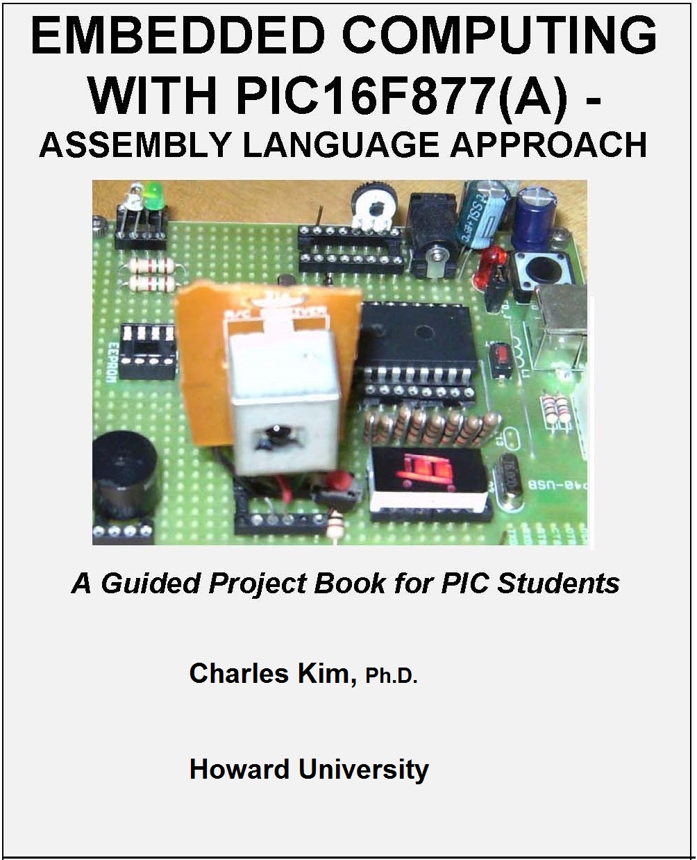
Embedded Computing with PIC16F877(A) -Assembly Language Approach
A complete guided project book for PIC students, 2006. p. 475
 Charles Kim, Ph.D.  contact: ckimson@gmail.com
Copyright Registration #: TX0008013944


What hardware components you must need [Read Carefully]:
Before your first coding practice, and before your long steps to the PIC programming, you have to check if you have everything you need. You don't want to stumble at the start line and you don't want to see your PIC engine fizzle out. Basically, you need four (4) things : (1) a PIC board - commercially available one or your own breadboard, (2) PIC burner - which downloads your code (or your bootloader code), (3) Bootloader code which you download to your PIC chip using the burner so that your application code can be downloaded without using the burner anymore, and lastly (4) a Windows program to actually download your code. Of course, you have to have PIC assembler, and you can get it free from Microchip web site. The exact name of the assembler (which comes with editor, assembler, and simulator, among other amenities) is MPLAB.
Check my PIC Start-up page for the detailed explanation for (1)what minimum hardware you have to have for your PIC project, (2) how to select a proper 16F877 or 16F877A chip for the project, (3) where you get a bootloader, (4) where you can find a PIC burner to burn your PIC16F877 or 16F877A bootloader, (5) where you can download the Windows-based PIC downloader program (which downloads your own hex code to the bootloaded PIC chip), and (6)other important stuffs you have to check before ignite your PIC engine - a must read for all beginners. Chapter 4 of the book describes step by step for this coding environment with sample codes.

About the Author: Dr. Charles Kim is a professor in the Department of Electrical Engineering and Computer Science at Howard University in Washington, DC, USA. He has taught for years both for undergraduate and graduate students at many universities including Texas A&M University, University of Suwon, and Howard University. Dr. Kim wrote this book originally for his Microcomputer course and Embedded Computing course, and currently this book is used as the textbook of Embedded Computing, which is basically project-based robot building course. It was also adopted for the Microcomputer course for assembly language programming. His approach in the book is simple: code in assembly language, which is free, instead of using C which costs you with cross compiler. Dr. Kim is active in embedded computing, smart sensor network, and AI and machine reasoning systems. Contact: ckimson@gmail.com for any question.

Table of Contents
 
Chapter 0: Book Cover, Table of Contents, and Preface
 
Chapter 1: Introduction Very skimpy introduction of 16F877. I thought a lengthy one waste of time or a little insulting to readers who I think are already exposed to the microcontroller. But everybody writes introduction, so I am kind of caved in by the peer pressure, and have my own introduction here. You can skip it without any loss.
 
Chapter 2: PIC16F877 Microcontroller - Overview This chapter is to shake loose your muscle as a relief pitcher does to record another save. This time it's one for PIC16F877. You learn about the architecture, pin and package, and block diagram that you can forget after the shake. Many things are done in hardware level, in which programmers bother to meddle with good hardware designers. The structure of program memory (RAM) and where special registers are already occupying in four different banks are important. Also important is where the empty RAM spaces ("file register") are located for our use. They are actually scattered in 4 different banks. Then we discuss how input and output ports are controlled to be used as input or output, with example codes. Very simple LED turn on and off code is presented to apply the I/O configuration. That's all, folks!
 
Chapter 3: Instructions Sets details PIC16F877 instruction sets. Bit- and byte-oriented instructions are explained with detailed examples. One example seems more effective than 1 page description, in my humble opinion. Instruction cycles and their period are briefed. Then, I add several tricks of using the instructions. The reason why we need tricks is that, first of all, PIC is centered around "peripheral", which means PIC is very good in dealing with inputs and outputs. But we are trained to calculate something using the instruction (PIC) which does not have much calculation instructions. We want to declare a variable as we do in C, like "long x", but how do we do that in PIC? How do I check if a certain bit in a byte is set or cleared? How can I check if an input from a motion detection sensor goes to zero or stays in high? Do we have DO loops or FOR loops or WHILE loops in PIC? How can I change the blinking frequency of an LED without using whatever is built inside PIC, I mean, using just simple instructions? These are the tricks. Every bit genuine, though.
 
Chapter 4: Coding Environment has some old and new pieces of information on the Microchip's coding environment, MPLAB. I liked the MPLAB v.5.2 very much and I loved the simulation. But V5.2 has problem with WindowsXP, so I start to teach V 6.40.  As you notice here that the environment is of OLD age.  No Windows 7 nor Windows 10.  So if you have a new MPLAB or an equivalent on your computer with a recent OS, skipping this chapter won't hurt.   Anyway, this chapter still has several pages of V5.2 and I think it does not, again, hurt anybody. I put the instruction of using the coding environment MPLAB in detail. I know you surely will agree to it. Then, I explain how you download the hex code generated from MPLAB into your PIC chip. For those who decided to build their own PIC board in a breadboard, I detail the minimum hardware for that. Use of MAX232 for RS-232 protocol and level conversion between the PIC chip and the serial communication port of your PC are detailed. I introduce a commercially available PIC board with either DB-9 serial communication port or USB port.  We know now that some laptop comes without the once standard DB-9 port. Instead it comes with USB port. so I add a few suggestions and recommendations when your port does not match with your computer's port. Of course, you have to pay some dollars to match the mismatch. I introduce PIC burner (a cheap but reliable one, which I currently use) and bootloader details. Also, I put all my PIC experiences at a section, Troubleshooting of your PIC board. It's worth reading. Then, I suggest a wire-wrapping method of circuit installation instead of usual soldering. Invest some money for your health. I hate to inhale the soldering smokes. Then, as if a bonus or gift, I happen to add a last section for a Piezoelectric buzzer example code. You'd like this complete code to test your PIC board, after testing with LED. Let your mom hear the buzzing and forgive your 3-year tuition money. She'd love to send you money for the last year of your education. [Note: If you start to use banksel to position to a proper bank for file register access, instead of the field manual way of p0 and p1 clearing or setting, be sure to remember that banksel does not like a company at its left: there must not be a label in the same line with banksel. Push up the label one line above. See the picture left for details.]
[An assembly code for push button-buzzer]


Chapter 5: Serial Communication If you are here, you have covered the basics of PIC programming. Not very good programmer, though. To become a good one, one has to know how to use PIC modules built inside the microcontroller. You can say a module a nice coffee machine. You select a coffee type, strong or bland, sugar or no-sugar for your taste by pressing a few buttons in a sequence. Then, slide your cup/mug and you have your coffee. PIC has numerous built-in modules for us programmers' easy use of the microcontroller. The first module we deal with is a module for serial communication, USART. To use a module, we have to know how to command the module to work for our purpose. But even before that, to know about the module's function is a must. Therefore, before the USART and its use for communication between PIC board and your PC, I give you a tour of serial communication first, at the first section. The famous serial communication protocol is RS-232 and one popular chip for level conversion between RS-232 and logic level is MAX232 chip. Then, I take you to how to use a Windows serial communication program, Hyperterminal, and set up for connecting your PC to PIC board. Then, the USART module. Its structure, internal registers we have to control, including the communication speed in bps (bit/sec), etc. Then, an example program follows to echo on your computer screen of the key-in you typed using your keyboard of PC. Sounds trivial? But it involves a lot more than just a trivial single key-in. The key-in read from keyboard travels first to your computer's serial port, then through the communication cable between your PC and PIC board, reaches at the MAX 232 chip, where the level is converted to logic level, and keeps moving to the serial communication pins of PIC chip. The USART module converts the serially transmitted bits into a single byte. This process is called a "read" in the PIC programming. You "read" but there is nothing in the screen. Since you do not write. The "write" a byte is exactly the reverse order to echo what you type. Anyway, the first example code will give your the full understanding of the subject. Serial communication between PIC and PC can be possible without using the USART module. Using the instructions and generating logic pulses can do the same as the USART module does. This is called "Software Serial." This is handy when you need more than one serial communication from PIC, like one to PC, and the other to another PIC board. I detail this software approach of serial communication with a full code. Sound knowledge in serial communication is a key to the many application examples discussed in the chapters to follow. So invest your time here. [An Assembly language code for RX-TX practice.]
Chapter 6: LCD Displaying and IR Remote Control Applications This chapter is long. It's because I have to explain a lot of stuffs. LCD is very popular and a convenient tool to display, replacing 7 segment LED modules. There are two types of LCD: a regular LCD and a serial LCD. A regular LCD is just the standard LCD module you can buy at $20 a piece. A serial LCD is the standard LCD module with something else attached at the back plane of the module and you pay $20 more for that something. By the way, you can take an LCD as a module which you can command to work for you. But you have to know how to bark your command, in bytes or, mostly, bits. There are two ways to connect the regular LCD to PIC. 8 wires between two and only 4 wires between two. We call them, "8 bit Interface" and "4 bit Interface", respectively. The serial LCD module is connected serially, that means via only 2 wires between PC and the serial LCD. How to command these monsters to work for you is the main subject of the chapter. Connection diagrams and coding examples are all over the chapter. Then, I decide to add Infra Red (IR) remote controller decoding example. Your TV/VCR remote controller sends code of signal, as you do in channel flipping, then an IR receiver hidden behind clouded plastic cover receives the signal and decodes ("breaking the code") and then flips the channel. How to receive the code from your remote controller and decode the message and display the message in your PC screen is the subject of the lengthy description of the subject. I start from different protocols of sending the code from your TV remote: Sony and Sharp as two famous ones. A step by step procedure for receiving, decoding, and displaying is covered. Hardware connection diagrams and full code are listed at the end of the chapter. Enjoy it. [Example assembly language code for LED control with Sharp remote controller]. [Example code for 20x4 LCD display with 4-bit interfacing.]
Chapter 7: Motor Control and Robot Project The subject sounds very heavy but controlling motors, whether DC, Stepper, or whatever, is rather light. Here I focus on motor control method of different type of motors. Then, I introduce motor control chips, which you can easily obtain (buy or get free as samples), and how to use the motor control chips to control the motors. The main point is to tell you how to send command to the chips, as we send command to IR receiver or a small guy like an LED. That's why motor control is such a small matter, according to me. One may think a stepper motor is in the different league. Well, there are stepper control chips, whether your stepper motor is unipolar or bipolar, which send a command for you to step around for a flamingo or samba. Several chips are introduced along with connection diagrams and example codes. So robot making does not seem too difficult after working on this chapter. If you are building a heavy-duty robot, like a battle-bot or a delivery robot, do not use the suggested chips: instead, buy a motor control panel/board and control it with your PIC.  Anyway, from this chapter, you can make a thing which can move. With IR on top, you can even remote control your thing. Great, isn't it? [Example code for unipolar stepper motor control with ALLEGRO UCN5804 chip].
Chapter 8: A/D Conversion and Data Acquisition Another built-in module we discuss here is an A/D conversion module. A/D means Analog-to-Digital, and which further means that the value we feel in the world must be changed to a digital number for PIC. Temperature or voltage can be measured by PIC. I labor to give you a good introduction of using the A/D module. Then, the first example, to practice, is voltage reading from a variable resistor powered by a DC 5 Volt source. So the max voltage you get is 5 Volt and the min, 0 Volt. Then, we display the result on PC screen. This involves a lot of coding actually. The example code will ease your job to understand the whole process. To further practice of A/D module, I introduce a distance finder example. Using an IR ranger, which generates voltage according to the distance, we apply the same A/D approach to display the distance of an object from the IR ranger. Connection of the IR ranger (Sharp GP2D12) and actual coding are presented. Also presented are some other parts and elements you can apply A/D to, and one of them is a current sensor. Well, you can use this module in many different applications. I bet. [Example Assembly code for reading voltage and displaying on the monitor.]
 
Chapter 9: Timer Modules and Digital Clock Applications Earlier (in chapter 4 in particular), we made out time delay using just using regular instructions. Here we study some modules for time delay and their application in digital clock. Only Timer0 module is heavily discussed: its use and command and control. LED blinking with Timer0 is the first example for a practice. Then comes many different versions of digital clock. Times are displayed on the computer screen. Then, we connect 4 buttons and LCD to the PIC for a serious digital clock. In the last Digital Clock project, with 3 buttons for Hour, Minutes, and Second setting and another button for "setting" itself, I introduce and apply PIC's external interruption pin (RB0/INT). Therefore, if you're interested in learning 'interrupt', this section of the chapter is the one you're looking for. As usual, connection diagrams and full code are scattered around the chapter. In the last section, I briefly introduce the use of Timer 1 and its application in color sensing. It's a very exciting practice. I got the color sensing chip free as sample and I think you'd do that too. [Digital clock example code.]
Chapter 10: Synchronous Serial Communication and Keyboard Connections Synchronous communication is run by a universal clock. And keyboard is connected and run with synchronous communication. I first discuss about the IBM AT or PS/2 type keyboard protocol. Then, with pain, I detail about display of key code sequence. This is essential to understand how to connect a keyboard to PIC board. Keyboard reading involves more than just reading a button or IR coding. You heard about "making code" and "braking code"? Display of keys as the first practice follows. This practice is the most important step. Read every line of my explanation and take pain to read every single line of the code. Then we move to the next section, Display of Key in LCD. This time, no computer is involved. Just your PIC board, a keyboard, and your LCD. You build a stand-alone system of keying and displaying, for example, by which your friend who is just rolled back after a several stitches in his mouth can type you what happened when you rush to a hospital. To make this stand-alone system, you may have to burn some oil first. It takes time to fully understand the process. Easier way, though, is just copy the code and download to your PIC. Impressive demonstration comes so easy.  However, I do not heartily endorse this easy path.  Again, take pain and get the gain, folks. And find much higher, nobler application for this exciting subject. [Example code for reading At or PS/2 Type Keyboard and displaying on the monitor.]
 
Chapter 11: Voice Synthesizer Project This chapter extends the previous chapter into voice generation from typed key. The main chip I use is DoubleTalk RC8650 Voice Synthesizer. I explain how to use the chip and provide coding example for RC8650. This time, the stand-alone system we built in Chapter 10 has an addition: voice. So the new system consists of PIC board, keyboard, LCD, RC8650, and a speaker. Now you can help hearing impaired people, too. And much more application in mind rushing through, I guess. Coding and diagrams and explanation of each segment of the code are provided, as usual. [Example code for RCS8650 voice synthesizer evaluation board]
Chapter 12: Internal EEPROM Access Inside PIC, there is a small size EEPROM(Electrically Erasable Programmable Red Only Memory). It stores only 256 bytes. This one can be overwritten, indefinitely, and keeps the data even after you turn off your power to PIC and finally get some much needed sleep when a gallon of coffee or tea cannot keep your eyes open. How we hate microcontroller programming, especially under the looming deadline. How to read from and write to the EEPROM is all about the chapter. As practice, I use telephone number storage and retrieval. If you are here, I know you are serious in PIC programming. And the success of your team is on your shoulder. So go out and get some stretch and come back to your desk. Good luck.[Example code for reading a 10-digit telephone number and storing them in to EEPROM Data Memory.]
Chapter 13: CCP (Capture/Compare/PWM) Module and PWM Pulse width modulation (PWM) is to generate a pulse of two different parameters: period and duty rate. Period of a pulse is composed of high duration and low duration. The high duration in a pulse period is called duty rate. In other words, you can make a pulse of 1 ms period. Out of 1ms, if you want to have 0.5ms high followed by 0.5 ms low, then your duty rate is 50%. Duty rate of 60% in 0.1 ms period will have 0.06 ms high duration followed by 0.04 ms low duration. PWM module of PIC allows you to generate a pulse with two parameters. Your job is to provide the two parameters in the terms the PIC and the PWM module understand. So the chapter talks just about that with sample codes. Whatever the application may be, motor control, voltage control, etc, you just provide the output pulse to the guy. By the way there are two PWM pins to be used. That means you can control two things at the same time. [Example code for PWM signal generation at CCP1 (RC2) pin using TMR2 module.]
 
Chapter 14: SSP (Synchronous Serial Port) Module and I2C Bus for External EEPROM (24LC16B -16K) Access I2C (Inter-IC) bus is very popular, particularly in home electronics products, TV, VCR, etc. The reason is that connection between processors needs only 2 or 3 lines, unlike 8 or more lines in the traditional internal bus configuration. I first discuss about the I2C bust and its protocol, and I guarantee that you hate this part. Complex and complicated. But I try to cut and untangle this mess. Then, we apply the I2C bus to a serial EEPROM which we connect to PIC. This serial EEPROM should not be confused with the small size internal EEPROM. The serial EEPROM we attach to PIC is 24LC16B which is 16K bit sized. If you have a lot of data to store and play around, this project is worthy of try. But mind you that it's complicated. But just follow my instruction and coding example. [Example Assembly Code: I2C Master Mode Program for use in 24LC16B Serial EEPROM access by 16F877].
 
Chapter 15: Armatron Control Armatron is an old technology, and chances are you have not heard about it. A few decades ago, this one came out with robotic arms on wheel. This chapter explains how to control the Armatron with your PIC alone. Simple relay control commands the Armatron to work: forward and reverse move, turn, pick up, etc. An IR receiver and a TV remote allow you to remotely command this antique. A student of mine cruises through this project with no sweat. You can do, too.
 
Chapter 16: Digital Control using PC with IR This project is interesting. We still use the subject of IR, but here IR is not just for reception, but transmission too. In other words, there are decoding and encoding of IR command involved using MC145026 (Encoder) and MC145027 (Decoder). Put simply, you can make your own remote controller. This project combines the IR reception and IR transmission via your computer for any simple control application. Another thing introduced here is a Windows based visual basic code for Windows interface for the command of IR. Provided are hardware description, details of complete code, and Visual basic code for Windows programming for serial Communication with 16F877.


   *NOTE:  Some slides of the above chapters may be found in the links:  ucF08, ucF09, and EMBedded


MWFTR.COM