www
EECE456 Embedded Systems Design Lab - Spring 2017
This course is sponsored by
Texas Instruments (TI)![]()
Instructor: Dr. Charles Kim
Texas Instrument 432 Resources:
MSP432 Launchpad, Educational BoosterPack MKII, CC3200 Launchpad - Wi-Fi Family, & Sensor Tag Development- CC2650 Wireless MCU, MSP432P401R Data Sheet
Link to MSP432P401R on Energia --- a must read
Link to a good or essential starter
MSP432P401R (Red Board) Development Kit --- a good read
TI MSP432 Launchpad (Manual)
TI MSP430/432 ----- Energia Setup for MacBook Users
Energia Language Reference (or Instruction Set)
Helpful Links:
energia.nu, Embedded Computing, EDUMKII Buzzer,
|
|
|
|
|
|
LABS
| LAB # | LAB Description | Components | Relevant Information |
Demo Date | Lab Report Due |
| 0 |
Development System Installation: After basic understanding of the TMP432 board ("Board") (through the Class note website and/or Web search) and thorough familiarity with what first to do in your computer and installation of the software development tool/kit so that the computer recognizes the Board. When connected via USB or mini-USB, run a sample
code (available from the software development kit/tool) of on-board LED
blinking and see if it works, and be ready for Lab0 demo. |
On-Board RGB LED of MSP432P401R Launchpad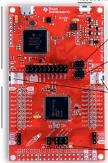 |
On-Board LED & TI MSP432P401R Launchpad |
W Jan 18 | N/A |
| 1 |
LED Color-Blinking:
After all required programming environment is completed and thus Lab 0 is
successfully done with a Red LED blinking with 1000ms ON and 1000 ms OFF, make out a blinking
of the on-board LED (this onboad LED used in the
example code of Blink is actually a color (or RGB) LED which can make out different
colors !!! Check how the
on-board LEDs are connected.) with different colors and different On/Off
periods. One example: Red (1000ms) - Off (100ms) - Green (200ms) - Off (100ms) - Blue (1000 ms) - Off (100ms). |
On-Board RGB
LED ("LED2")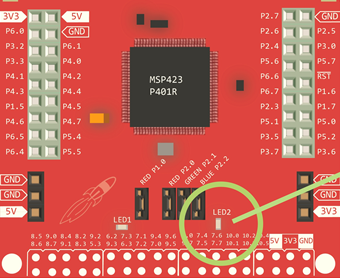 LED2 LED2 |
On-Board LED | W Jan 25 | W Feb 1 |
| 2 |
LED Blinking Rate Control by Analog
Sensor: Control the on-board RGB LED's blinking rate by the sensed
value of an analog sensor. One type of analog sensors will
be provided. Blinking of a single color is good enough. |
On-Board LED Grove Rotary Angle Sensor Grove Photosensor 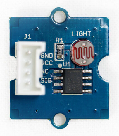 Grove Temperature Sensor |
On-Board LED, Grove Rotary Angle Sensor, Grove Photosensor, Grove Temperature Sensor |
W Feb 1 | W Feb 8 |
| 3 |
LED Blinking Rate and Color Control by Analog
Sensor and Digital Input: Control the on-board RGB LED's blinking rate
and the color by the sensed
value of an analog sensor and the digital input from a digital input
sensor. One type of digital input sensor will
be provided. The rate of blinking is to be controller by the read
value of the analog sensor, and the color must be changed from Red to
Yellow to Green to Blue to White and back to Red at each time the input
is sensed. Photosensor Grove Temperature Sensor |
On-Board LED Grove touch sensor 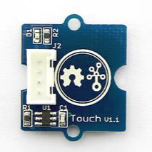
Grove Button 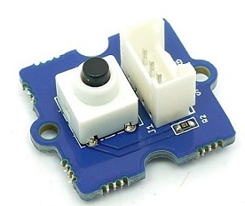
Grove Rotary Angle Sensor |
Grove Touch Sensor, Grove Button |
W Feb 8 | W Feb 15 |
| 4 |
LED (External) Blinking Rate and Color Control by Analog
Sensor and Digital Input:This lab is identical
to Lab3 except that the On-Board LED is not used here but, instead, an external RGB LED
module called
ShiftBrite V2.0 from Macetech is to be used. Grove touch sensor Grove Button
Grove Rotary Angle Sensor |
ShiftBrite
V2.0 RGB LED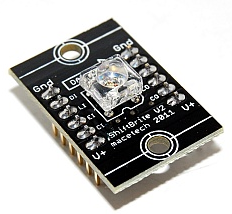 Grove Photosensor Grove Temperature Sensor |
ShiftBrite V2.0 from Macetech ShiftBrite Coding Example Document on ShiftBrite Energia Core Libraries |
W Feb 15 | W Feb 22 |
| 5 |
Distance Indication by External LED. This Lab uses the external
LED to indicate a distance of an object from a Sharp Infra-Red (IR)
distance Senor [model: GP2Y0A21YK0F] . The push-button or
touch-sensor is for Activation or Deactivation mode of the LED
indication of the distance. Specific instruction: (a) The starting mode is Activation (b) In Activation mode, if the distance of an object is farther than 80 cm turn LED on GREEN, if the distance is between 80 cm and 40 cm, YELLOW, and if closer than 40 cm, RED. (c) During the Activation mode, if a push-button (or touch-sensor) is pressed, then the mode is changed to Deactivation (which means LED is turned off while continuing the distance monitoring - which has to be evidenced through the Serial Monitor showing distances in cm unit). (d)In Deactivation mode, if a push-button is pressed, then Activation mode resumes. |
Sharp IR
Distance Sensor GP2Y0A21YK0F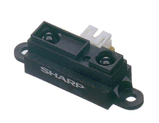 ShiftBrite V2.0 RGB LED Grove touch sensor Grove Button
|
Sharp IR Sensor
GP2y0A21YK0F Download& Document Site for Sharp IR Sensor (with Example Codes) |
W Feb 22 | W Mar 1 |
| 6 |
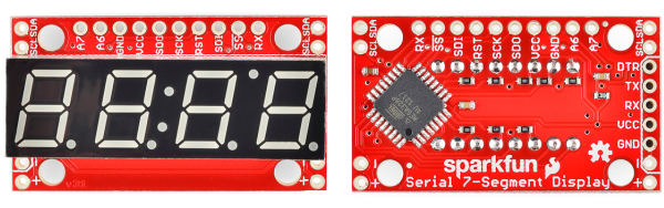
Distance Indication on a 7-Segment Display. This Lab uses a
Serial 7-Segment Display (Sparkfun
Part no. COM-11441) to display a distance of an object from the same Sharp
Infra-Red (IR) distance Senor used in Lab 5. The
push-button or touch-sensor is for Display or No-Display mode of the distance
display on the 7-Segment Display. Specific instruction: (a) The starting mode is Display Mode. (b) In Display Mode, display the distance on the 7-Segment Display in cm unit. (c) During the Display Mode, if a push-button (or touch-sensor) is pressed, then the mode is changed to No-Display Mode (which means no-display of distance on the 7-Segment Display while continuing the distance monitoring - which has to be evidenced through the Serial Monitor showing distances in cm unit). (d) In No-Display mode, if a push-button is pressed, then Display Mode resumes. |
 Sparkfun Serial 7-Segment Display Sharp IR Distance Sensor GP2Y0A21YK0F Grove touch sensor Grove Button
|
Sparkfun Serial 7-Segment Display (Introduction) Pins and Their Uses for Different Communication Protocols. SPI/I2C Libraries and Examples for Energia (at GitHub) |
W Mar 1 | W Mar 8 |
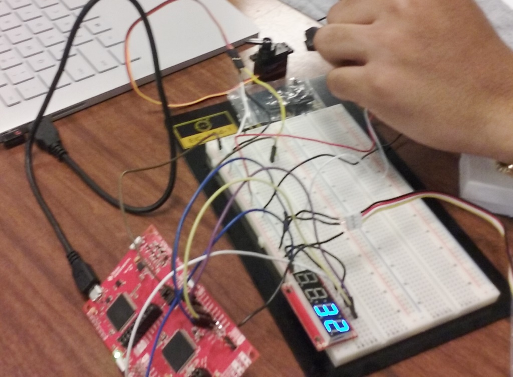
| 7 |
Servo-Motor Control & Distance Display. This Lab, in addition to
the a Serial 7-Segment Display and Sharp
Infra-Red (IR) distance Senor used in Lab 6, connects a micro-servo
motor (P1143 of Adafruit). The
push-button or touch-sensor is for Active or Silent mode of the Lab, its
details explained below. Specific instruction: (a) The starting mode is Active Mode. (b) In Active Mode, display the distance of an object on the 7-Segment Display in cm unit and turn (0 to 180 degrees and 180 to 0 degrees) (Left to Right) (Right to Left) the servo-motor with a speed proportional to the distance: The farther an object is from the distance sensor, the faster the covering of the 180 degrees, in a forward and backward motion, of the servo motor, and vice versa. However, if the distance is 20 cm or shorter, stop the servo motor wherever the position may be. Also, any distance farther than 70 cm should have the same servo turning speed (covering 0 - 180 degrees and 180 to 0 degrees) as at 70 cm. (c) During the Active Mode, if a push-button (or touch-sensor) is pressed, then the mode is changed to Silent Mode (which means the servo motor stops its turn immediately while the distance display on the 7-Segment Display continues). (d) In Silent Mode, if a push-button is pressed, then Active Mode resumes and the servo turns toward Right first from the stopped position. Grove touch sensor
|
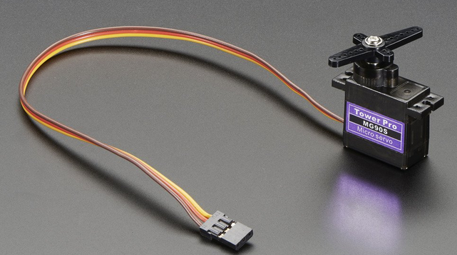 Adafruit Micro-Servo High Torque Sparkfun Serial 7-Segment Display Sharp IR Distance Sensor GP2Y0A21YK0F |
Adafruit Micro-Servo
Motor P1143 Servo Libraries for Energia (at GitHub) Example: Spin the Servo (Energia) |
W Mar 22 | W Mar 29 |
| 8 |
Distance Measurement by Ultrasonic Sensor and Display in the
Distance on a 7-Segment Display. This Lab uses the same
Serial 7-Segment Display the previous labs have used to display a
distance of an object from an Ultrasonic Sensor (HC-SR04). The
range of distance is 2 cm to 400 cm, therefore the Display should be
able to cover the entire range in cm unit. The Mode for this Lab
is always Active More - there is no push button required for Mode
switch. *Optional component (Voltage-Level Translator: 3.3 V <--> 5.0V) |
Ultrasonic
Sensor: HC-SR04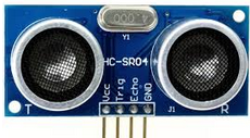 Sparkfun Serial 7-Segment Display |
HC-SR04 Example 1 Example2 - with i8051 (for good understanding of how it works) |
W Mar 29 | W Apr 5 |
| 9 |
Display of the distance on Serial Monitor of one party measured with
Ultrasound sensor by the other party, and vice versa, via RX (p3.2)
and TX (p.3.3) of UART (Universal Asynchronous Receiver Transmitter).
This Lab requires 2 groups to work together. UART communication can
be done by physically connecting TX pin of a MSP432 board to RX pin of
the other MSP432 board with a wire, and RX pin of the former to
TX pin of the latter. Each party must be able to send and receive
data over the UART pins. For a smooth exchange session, one must
start with Transmitter Mode and the other Receiver Mode.
Details are as follow: Transmitter Mode: Measure the distance from the Ultrasound Sensor and send the measured value in cm unit to the other party via UART. After a transmission is done, without any wait or time delay it change its mode to Receiver Mode. Receiver Mode: Receive data from the other party via UART and display the data to the Serial Monitor screen. Then, after 1 second time delay, it changes to Transmitter Mode. 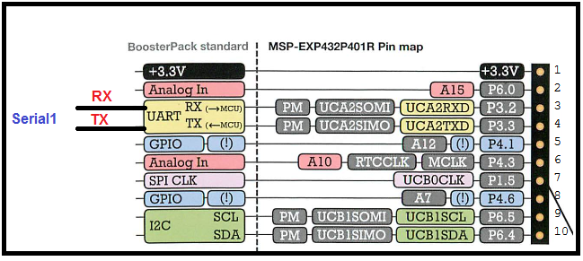 |
Ultrasonic
Sensor: HC-SR04 |
Transmitter Sample Code (as a
text file): this code transmits 'H' and 'L' alternatingly to a
receiver. Receiver Sample Code (as a text file): this code receives data from the transmitter, then turns on an LED if the received data is 'H', and turns off the LED if 'L'. |
W Apr 5 | W Apr 12 |
| 10 |
Display of the distance on Serial Monitor of one party measured with
Ultrasound sensor by the other party, and vice versa, using
NRF24L01+ 2.4 GHz Wireless RF Transceiver Module. As in Lab 9, this Lab requires 2 groups to work together.
But transmission is done by manual key-in. Each party must be able to send and receive data via radio
communication, but transmission can be made only when character 'T '
is typed on the serial monitor. Therefore, both parties must
start with Receiver Mode.
Details are as follow: Receiver Mode: Receive data from the other party via Radio and display the data on to the Serial Monitor screen. A transition to Transmitter Mode is made possible by typing 'T' on the serial monitor screen. Transmitter Mode: Measure the distance from the Ultrasound Sensor and send the measured value in cm unit to the other party via Radio. After a transmission is done, without any wait or time delay it change its mode to Receiver Mode. |
NRF2401+
2.4HGz Wireless RF Transceiver Module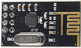 Ultrasonic Sensor: HC-SR04 |
Wiki on
How
To NRF24L01 Example (with Arduino) Enrf24 Library Zip file (NOTE: Read this Instruction before you install) Transmitter Sample Code Receiver Sample Code |
W Apr 12 | W Apr 19 |
| 11 |
Display of the distance on Serial Monitor of one party measured with
Ultrasound sensor by the other party, and vice versa, using
NRF24L01+ 2.4 GHz Wireless RF Transceiver Module, and following our own
"456
Protocol".
As in Labs 9 and 10, this Lab requires 2 groups to work together.
But transmission is done by manual key-in. Each party must be able to send and receive data via radio
communication, but transmission can be made only when character 'T '
is typed on the serial monitor. Therefore, both parties must
start with Receiver Mode.
In data exchange, 456 Protocol should
be observed (and data be displayed on Serial Monitor screen, not
LCD). Receiver Mode: Receive data from the other party via Radio complying with the 456 Protocol and display the data on to the Serial Monitor screen. A transition to Transmitter Mode is made possible by typing 'T' on the serial monitor screen. Transmitter Mode: Measure the distance from the Ultrasound Sensor and send the measured value in cm unit to the other party via Radio complying with the 456 Protocol. After a transmission is done, without any wait or time delay it change its mode to Receiver Mode. |
NRF2401+
2.4HGz Wireless RF Transceiver Module Ultrasonic Sensor: HC-SR04 |
456 Protocol Lab 11 Demo Check Process |
W Apr 19 | W Apr 26 |
| X | Extra Credit Lab (for a team of 3 groups): Multi-Party Texting via Radio. This free, extra-credit lab is to establish and demonstrate multi-party texting system using (1) NRF24L01+ 2.4 GHz Wireless RF Transceiver Module, (2) Serial Monitor Screen, and (3) 456 Protocol. Three (3) groups are needed to form a team and work together. A text message from a party must be directed to just one party at a time - no broadcasting - and should be able to repond selectively. Mode setting (or no mode at all) is all determined by the team. After forming a team (of 3 groups), notify with a list of groups joining the team. | NRF2401+
2.4HGz Wireless RF Transceiver Module |
Demo by Appointment (Graduating seniors: by April 26;
Others: by May 2) |
Individual
Report Submission: (Graduating seniors: by April 27; Others: Within 2 days after Demo ) |
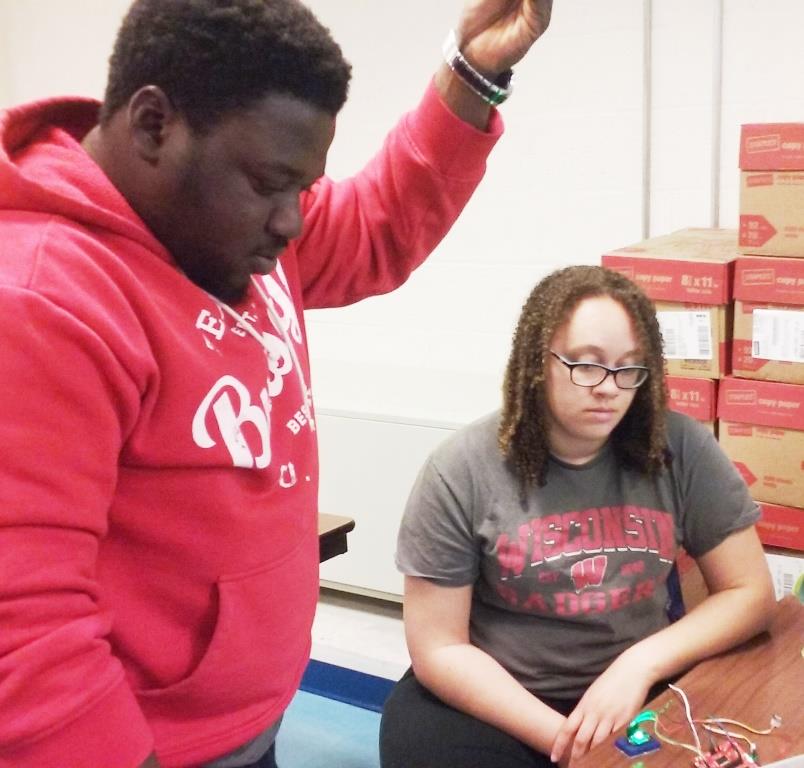
Gallery
Lab4
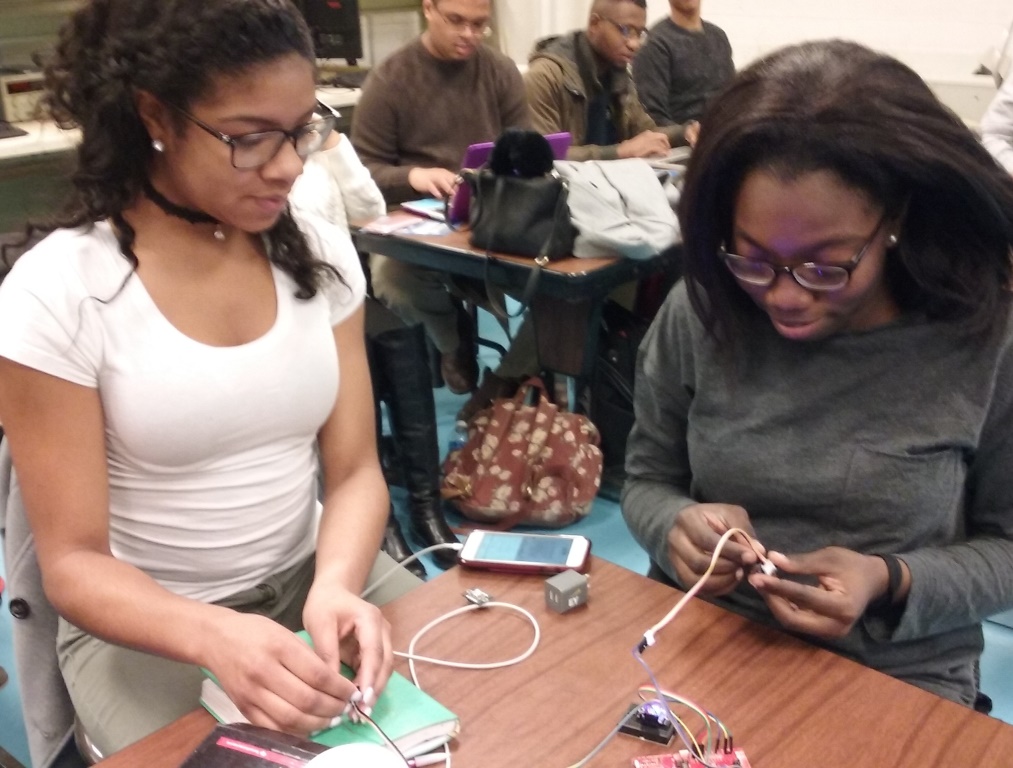
Group2:Breyonna Pinkney and Mercy Daniel-Aguebor
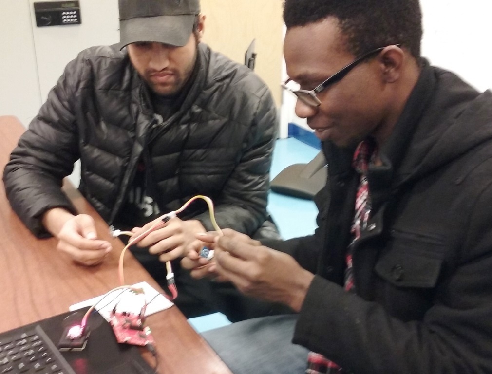
Group 8: Jonathan Goberdhan and Conrad Blash
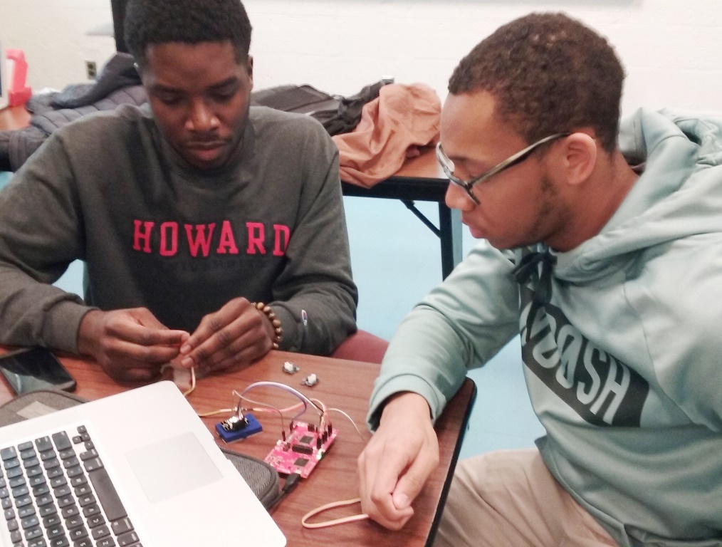
Group 6: Alozie Pat-Ekeji and Malmcolm Friday. Group 9: Jordan Lafontant and Shamar Christian
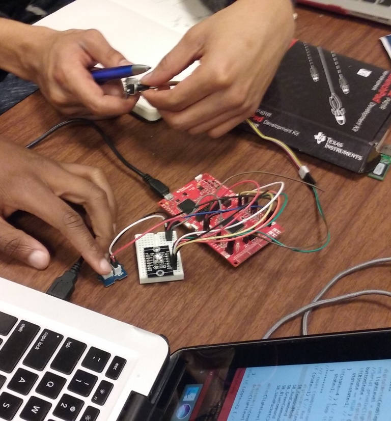
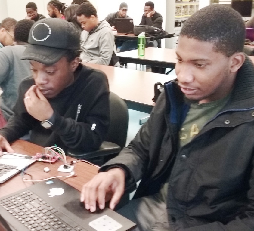
Lab7
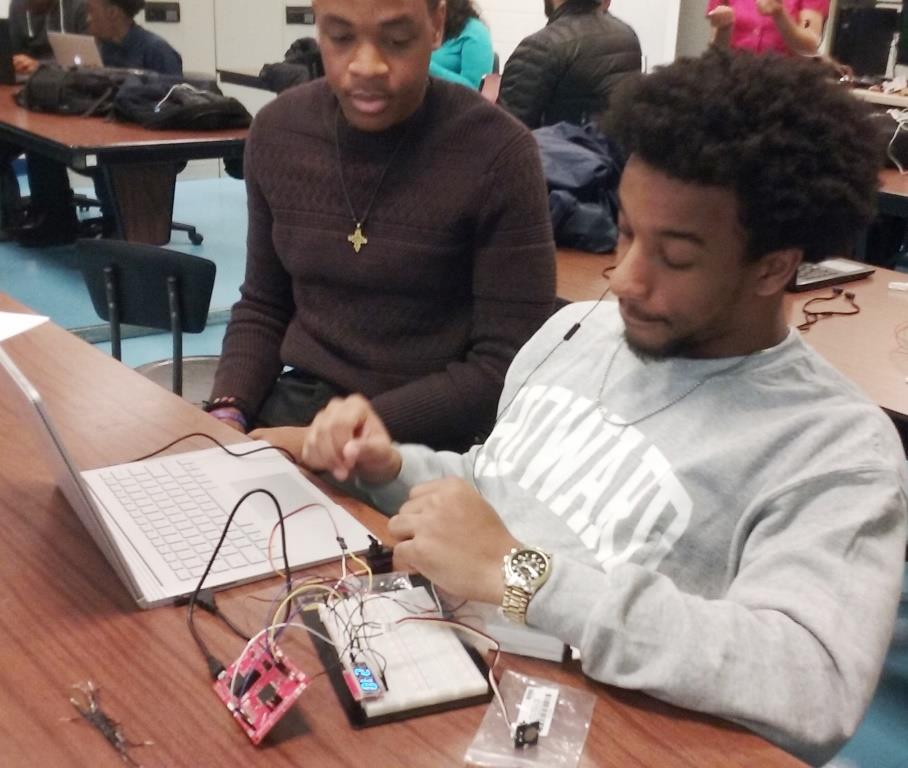
Group3: Calude Julien and Quentin Cola.
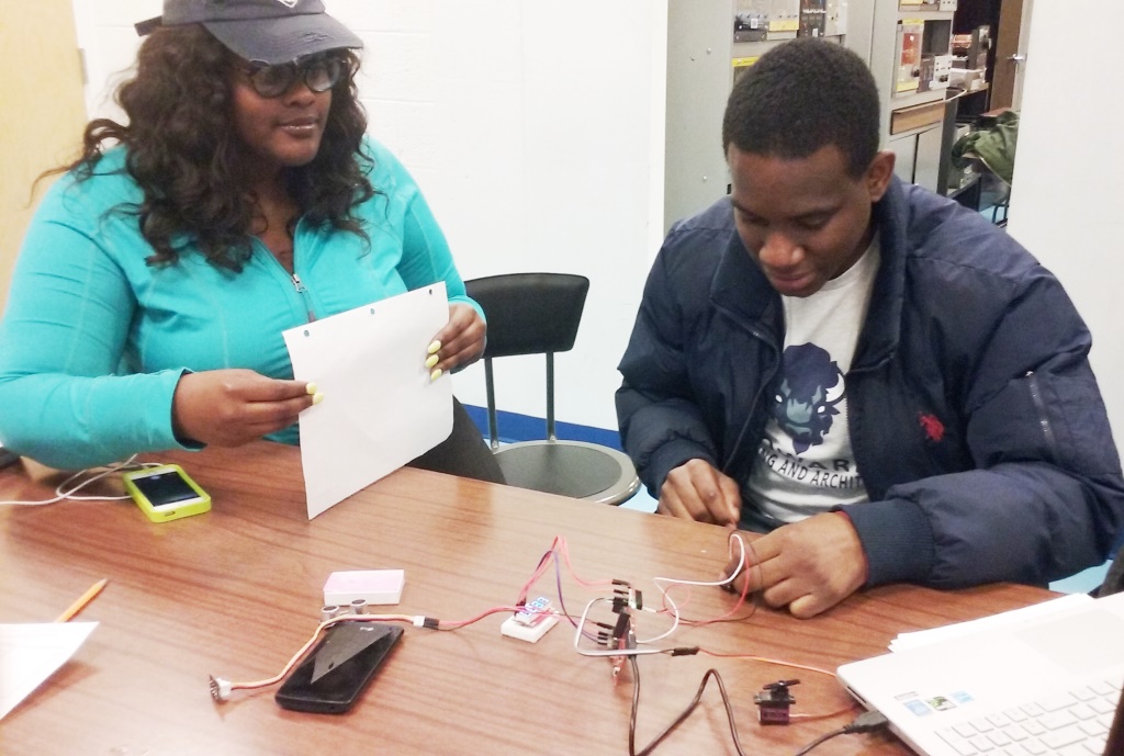
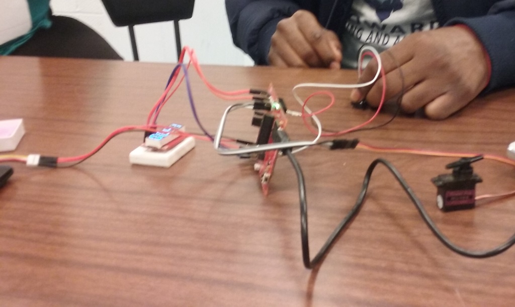
Group 7: Kelsey Logan and Shelton Allen.
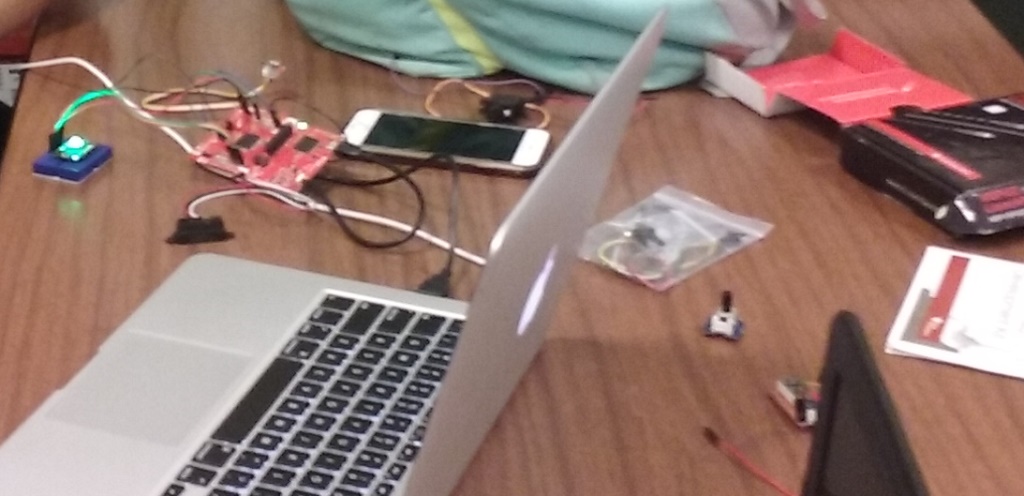
Group 10: Oluwafolajimi Onadeko and Elise Blackmon
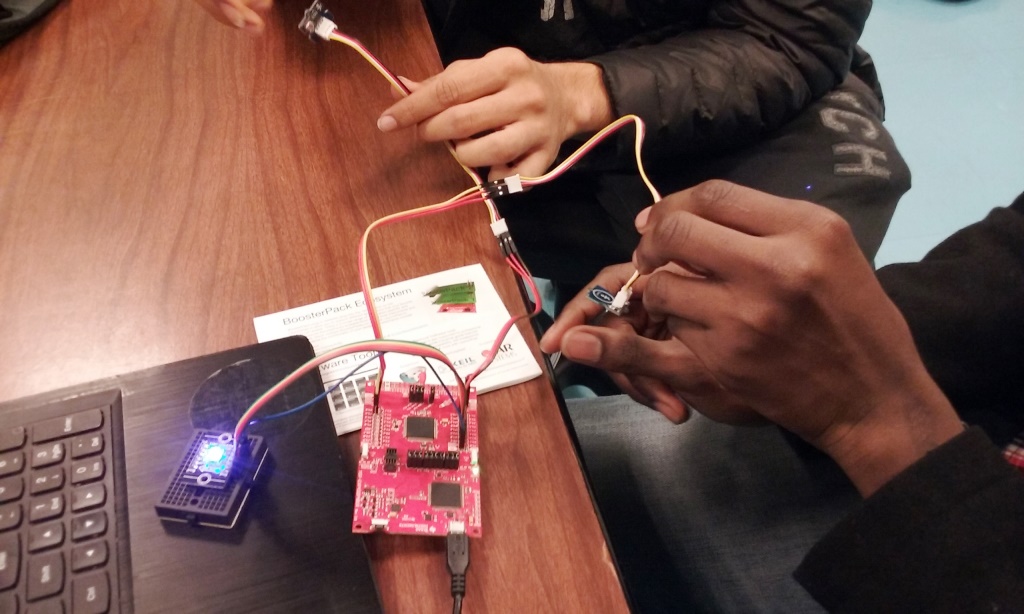
Lab 11
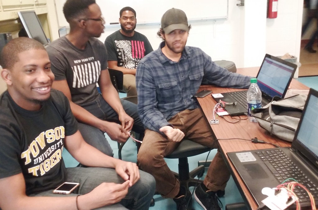
From Left: Shamar Christian, Conrad Blash, Kolby Lacy, and Jonathan Goberdhan.