The Laws of Circuit - you can learn and practice by just reading
Copyright. Charles Kim 2006
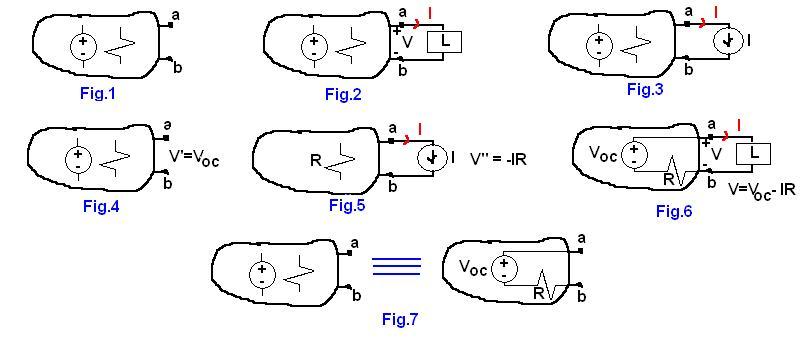
For those who are interested in the voltage between a and b, when the current amount is I, it does not matter the current I is resulted from the total source of the circuit and the total resistance of the circuit and the load, or the current is resulted from a current source in the load. In other words, assuming that the circuit side and the load side are separated by a curtain, if you are watching at the terminal a, and you observe the current amount I, then do you think you know what is there at the right side over the curtain? You'd safely guess that there is a current source of I. Therefore, the load, which determines the current amount of I, can be replace by a current source (Fig.3). (*Warning: This is for the proof purpose only. Do not apply this analogy in your circuit problem solving. Since there will be no curtain in your circuit problem). Fig.3 now becomes a two source problem. In other words, the voltage between a and b is determined by the source inside the circuit and the current source. As you remember, we can apply the superposition principle here. Let's consider the circuit (voltage) source only (Fig. 4). So we deactivated the current source by taking it out of the terminals. The terminal voltage contributed by the internal voltage of the circuit is the open circuit voltage at the terminals (the terminals are open), so we can say V' = Voc. Now, let's deactivate the internal voltage source of the circuit, and put the current source back to position to calculate the contribution of the current source alone (Fig.5). Since the current I flows through, the equivalent internal resistance (after deactivation of the internal source) can be represented by a resistor R. Then, the terminal voltage is V''= - IR. Why the negative polarity here? By following the passive convention, since current flows from b to a through the internal circuit, polarity (+) is on b and polairty (-) is on a for the voltage. That's way Vab is a negative value. Therefore the overall terminal voltage is sum of the two contributions: V=V' + V" = Voc - IR. If you consider that the terminal voltage is given by Voc - IR, you can now guess the formation of the source and resistor inside the circuit: the source of Voc and resistor R are connected in series, so that the voltage at the terminal is the voltage source Voc minus the internal resitance (R) times the current (I). Therefore, as conclusion, the circuit can be replaced by an open circuit voltage (which is Thevenin voltage) and a series resistor R (which is the equivalent circuit after deactivation of all internal sources.). Bottom line: Fig. 7 says that a circuit can be converted to a Thevenin equivalent circuit, which has a Thevenin voltage (Vth = Voc) and a series resistor (R = Rth).