![]()
EECE456 Embedded Systems Design Lab - Spring 2016
This course is sponsored by Intel Corp.
Texas Instrument is appreciated for donating some equipment for the class
Dr. Charles Kim
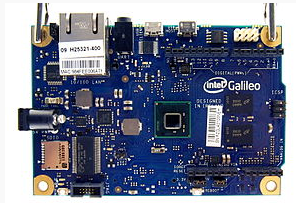
Intel Galileo Resources:
 Gen
1
Gen
1
Intel Galileo Development Board and Intel Galileo Learning Center (A Good Source!)
Galileo- Getting Started (and Tutorial for Mac Users)
Intel Galileo Workshop (Very Good Source when you have IDE installation problem)
Introduction and First Application - by Emmanuel Ademmuwagun
Arduino Language Reference (or Instruction Set) for Galileo
Galileo Troubleshooting (Intel Community) : NOTE -- It is recommended that, if your PC has Arduino System, you remove Arduino before your install the Intel Galileo Software Development System
Texas Instrument MSP430/432 Resources:
(*Other available boards and kits: MSP432 Launchpad, Educational BoosterPack MKII, CC3200 Launchpad - Wi-Fi Family, & Sensor Tag Development- CC2650 Wireless MCU)
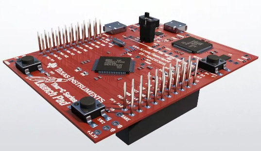
TI MSP430 Launch Pad Instruction (Manual)
TI MSP430 Launch Board - TUTORIAL
Download: Driver for 32-bit machine and 64-bit machine) ["Save as"] (and you need these 2 files too: .cat and .inf)
Link to Energia IDE
Slac623e.zip file (mentioned in the Troubleshooting section, pp. 28-29, of the Tutorial on MSP430 above): Link or Download ["save as"]
TI MSP432 Launchpad (Manual)
TI MSP430/432 ----- Energia Setup for MacBook Users
Energia Language Reference (or Instruction Set)
MSP430 LaunchPad Tutorial (TI wiki)
Intel Edison Resources:
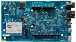
Intel Edison - One Tiny Module, Endless Possibility
Intel Edison - Step by Step Setting Up
Driver for Intel Edison (* Come see your instructor with a Thumb Drive)
LABS
Lab Report Format (any hint for drawing a manageable schematic diagram?)
Lab1- LED Blinking: [Check/Demo Date: Feb 1] Connect one input device (such as a photo-sensor, push button, potentiometer, toggle switch, etc.) to your platform, and write a code which changes the rate of LED blinking by different value/position of the input device. For the Galileo, pick one from the Grove Kit box. For other platforms (TI and Edison), an input component can be arranged by the instructor or can be borrowed from a Grove Kit holder. The report of this lab, following the Lab Report Format, must be submitted by Feb 8 (M) in an electronic medium. More information (manuals, sample codes, etc) on Grove sensors can be found here.
Lab2 - Variable LED Blinking Rate & Buzzer : [Check/Demo Date: Feb 8] Before starting this Lab, make sure your input device (from Lab1) is an analog device which produces continuous values. Examples of analog input device include, but not limited to, light sensor, potentiometer, and sound sensor. If you connected in Lab 1 a digital device such as button or touch sensor, make sure you connect an analog device to your board and try to re-write your code so that Lab 1 works. (* Your report on Lab 1 does not have to change to reflect the input device change.) If you do not have a Grove kit, contact the instructor for an analog input device. However, you can make your own analog device using several resistors serially placed on a breadboard (what is a breadboard?). Now, connect a buzzer to the platform of analog-device connected Lab1, and write a code which, by different value/position of the input device (of Lab1), changes the rate of LED blinking and makes the buzzer buzz only during the ON period of LED blinking (thus, making the buzzer and LED synchronously respond to input variations). For Galileo, pick the Grove Kit buzzer. For other platforms (TI and Edison), a Piezo-buzzer can be arranged by the instructor. The report of this lab, following the Lab Report Format, must be submitted by Feb 16 (T) in an electronic medium.
Lab3 - Color LED Control: [Check/Demo Date: Feb 29] While we continue to add more components, there is one exception - remove the noisy and annoying buzzer before we move on to this Lab 3. So now in the start line, we have only these 2 components: an LED (green or red depending on platforms) and an analog input device (photosensor, potentiometer - Grove or Your Own, etc.).
Here goes the Lab 3 proper. Now add to your system a color LED module: SparkFun RGB LED Breakout - WS2812B (BOB-13282). You need to read and know the features of this RGB LED module and how this module can be controlled. Check this LINK to learn about WS2812 Breakout Hookup Guide and (near the bottom of the webpage of the link, under Resources, find) Libraries and Sample Codes from Adafruit (download zip file "Example Code and NeoPixel Library").
For further and better understanding the libraries, you may have to click the next one, "Adafruit NeoPixel Library Github" and from there, you may need to read a few files including, Adafruit_NeoPixel.h, and more importantly, Adafruit_NeoPixel.cpp, which will reveal the functions called in the example Arduino code, and how the exact pulse timing is obtained by the CPU clock speed of different microcontrollers. Soldering (Is there a soldering station in the building?) is required to connect break away straight headers to the breakout board. Also, you need jumper wires. Also, don't forget a capacitor between power and the ground pins to avoid burn-out of the LED module. All these components will be distributed in the class.
Now programming part: write a code which, by different values/positions of the input device, changes the rate of LED blinking and synchronously causes variation in the RGB LED. Make sure your finished lab utilizes ALL the features of the RGB LED module. The report of this lab, following the Lab Report Format, must be submitted by Mar 7 (M) in an electronic medium.
Troubleshooting? Start from Intel Galileo in the Arduino's View. Also Arduino Language Reference (or Instruction Set). By the way, are you suspicious of the slower speed of the Galileo I/O pins (compared with Arduino's) as the main cause of your problem ? - Read this (in graphic format) or this (in pdf format)and gain something and solve your problem. For TI Platform, go check again the Energia Language Reference page.
Lab4 - Color LED Control 2: [Check/Demo Date: Mar 7] This lab is identical to Lab3 except that that the SparkFun RGB LED is replaced by another RGB LED module called ShiftBrite V2.0 from Macetech (Document on ShiftBrite). Again, for this Lab4, all the requirements for connection (with ShiftBrite replacing SparkFun for RGB LED module) and coding are the same as Lab3. A ShiftBrite module (no soldering required) and a few more jumper wires will be distributed in the class. The report of this lab, following the Lab Report Format, must be submitted by Mar 21 (M) in an electronic medium.

Lab5 - LCD and LED Blinking Rate: [Check/Demo Date: Mar 21] This Lab is about connecting an LCD module. There are only 3 components connected to a platform: (1) LED (either on-board or external one); (2) an analog input device (like the one used in the previous labs); and (3) an LCD module. The requirement of the Lab: Write a code which, by different values/positions of the analog input device, indicate/display the LED blinking rate (such as "RATE = 1 second, 200 ms, etc") on the LCD screen, and make the LED blink at the said rate.
For a LCD module, a Galileo (or Edison) user picks a Grove-LCD RGB Backlight from the Grove box. Gove-LCD RGB LCD users must utilize the color feature of the module in indicating the LED blinking rate in different ranges.
For TI platform users, there are a few modules of Grove-LCD RBG Backlight LCD available, but the majority of TI platform users must use mono-color LCDs of this type - 16x2 Parallel Character LCD from Crystalfontz. Gove-LCD RGB LCD users must utilize the color feature of the module in indicating the LED blinking rate in different ranges.
These parallel LCDs are those installed in the Intel DE2i-150 Board, and pulled out from bad/burnt boards. This Parallel LCD is, in terms of operation and interface to platform, very different from the Grove-LCD. The Grove-LCD, a Serial LCD, is interfaced using Inter-Integrated Circuit (I2C) protocol via only 2 lines (in addition to Power and GND) - SDA and SCL. On the other hand, the Parallel LCD is interfaced with either 4 data lines or 8 data lines.
The pinout of the Crystalfontz 16x2 Parallel Character LCD must be known from this Crystalfontz Link or this PDF File before any wiring/interfacing action (See Figs 1, 3, and 4, and find out the PIN functions of the 14-pin connector).
Even though you may be able to find a sample code (like this or this or this) to start with, this excerpt of a Chapter on Parallel LCD from my e-book Embedded Computing with PIC 16F877 - Assembly Programming Approach would help you completely understand LCD controlling. This link looks helpful too. The report of this lab, following the Lab Report Format, must be submitted by Mar 28 (M) in an electronic medium.
Lab6 - Texting Via Serial Communication: [Check/Demo Date: Apr 4] This Lab is about writing a code for connecting two platforms via serial communication (TX and RX pins) [link to serial communication tutorial from SparkFun] so that a text message sent from a platform is received and displayed in the other platform. As for components, this lab requires the following 4 components: (a) 2 LEDs (one red and the other green color), (b) an analog input device; and (c) an LCD module. The message communication for this lab should follow our class' own 456 Protocol. The completed work should function as follows:
(1) a platform works at a given time as one of the two modes: transmitter or a receiver (but not both);
(2) one time selection (right after uploading of the code or right after a reset button is pressed and releases)of the initial mode for transmitter or receiver is done by the position of the analog input (for example, a value or a position below a certain threshold would set the platform as a transmitter and a value higher as a receiver, or vice versa);
(3) the LEDs in different color should indicate the selected mode in the following manner: {Red LED ON - Green LED OFF} for transmitter and {Green LED ON - Red LED OFF} for receiver mode; How to connect LEDs to your platform pins (especially you do not have Grove-Kit provided LEDs)? Check here.)
(4) When the transmitter mode is selected, the code first pause for 2 seconds, then sends a secret text message (embedded in the code), following the 456 Protocol, of maximum 12 letters or numbers or combination of them at the speed of 9600 bps, repeatedly 3 times with 500 milli-second pause between messages and, after the transmission is completed, immediately changes its mode to receiver;
(5) When the receiver mode is selected, with no delay, the code receives at 9600 bps the data stream (remember that there are multiple number of but the same text message coming in) and, at the end of the data receipt, decodes the data stream by the 456 Protocol, displays the Sender ID only (when the message is inteded for another platform) or Sender ID and the message (when the message is intended for the platform) on the LCD and, after the receipt and display is done, pauses 2 seconds and changes its mode to transmitter.
As a starter, interesting tutorials are found: For Galileo: here, and here and here (for Arduino). For TI Platform: here fore Energia Serial and here for an MSP430 -Serial tutorial. Also, the TI wiki on MSP430 LaunchPad Tutorials treat Serial Communication rather extensively. The testing of this lab will be conducted with two platforms paired with TX and RX pins cross-connected. Pairing for the test is up to the pairing parties. The report of this lab, following the Lab Report Format, must be submitted by Apr 11 (M) in an electronic medium. Each student should write and submit one's own report.
Lab7- Wireless Texting: [Check/Demo Date: Apr 18 ] This Lab (done in 2-person groups, except 2 persons in different platforms) is about writing a code for a two-point or multi-point wireless texting system using one of the following wireless transceiver modules: Bluetooth, Radio-Frequency (RF) Transceiver, or Zigbee. There are 3 components connected to a platform: (1) LED (either on-board or external one); (2) a wireless transceiver module; and (3) an LCD module. For Bluetooth and RF, two-party texting is to be realized, and for Zigbee, multi-party texting. Incoming and outgoing texts are to be displayed on the LCD. And the LED (blinking) should work as an alert for incoming test message.
For Bluetooth, RN-42 Bluetooth Module from Parallax is utilized (a quick guide and a thick manual for the module).
For a RF transceiver module, 433MHz RF Transmitter/Receiver Pair will be used for this lab (a short data sheet and a good tutorial on the 433 MHz RF module with Arduino).
As for Zigbee (What's Zigbee?) module, Digi International's XBee multiport RF Module is selected (XBee module datasheet from SparkFun, Arduino Wireless SD Shield, and Library for Digi XBee Radio at GitHub).
The groups and testing-brackt for the lab is depicted here (Lab7 Test-Bracket). The report of this lab, following the Lab Report Format, must be submitted by 5:00pm Apr 22 (F) (for Prospective Graduates) or by Apr 25 (for the rest of the class) in an electronic medium. Each student should write and submit one's own report.
Lab8- Internet Enabled Application [Demo/Check: May 2 (M)] This lab, about Ethernet (for Galielo Gen 2) or Wi-Fi Connection (for Intel Edison or for TI CC3200 LaunchPad), is done in groups works. The groups and their platforms are depicted here (Lab8 Groups). The groups are encouraged to acquire the platforms as early as possible so that they get familiar with the new paltforms before this lab starts. The content of this lab is open - a system integration for any application is acceptable as far as the platform is Internet-connected. Previously, some students controlled the blinking rate of an LED or the flow rate of a water pump (toy size, of course) in the platform (Galileo Gen 2 for example) from a remote desktop (actually one in the Lab).
For Galielo Gen 2 group, a good starter and very good tutorial is available here (Ethernet Access and Remote Control with Intel Galileo). Here is the Intel Edison Wi-Fi Guide.
Groups with the new TI platform CC3200 LaunchPad should consider spending more time than usual to prepare with CC3200 SDK, IDE, Simple Link Wi-Fi Starter, and other necessary software development tools such as IAR Embedded Workbench Kickstart. Also visit TI Dev Site. Each student should write and submit one's own report.
[Report Due: 2:00pm May 9)]